Transcription courtesy of DeLorean Directory
Systems Analysis Approach to Integrating Air Bags Into a Production Ready Small Car
Michael U. Fitzpatrick
Fitzpatrick Engineering
Route 5, Box 495A
Warsaw, IN 46580
Contract No. DTNH22-81-C-07330
Contract Amount $24,685
This document is disseminated under the sponsorship of the Department of Transportation in the interest of information exchange. The United States Government assumes no liability for its contents or use thereof.
Click here for the PDF of the original file.
Dynamic Science, Inc. (now Exponent) appears to have done the testing.
Abstract
During the course of this study test data derived from Contract No. DINH22-81-C-07330 was use to further validate the computer models “DRACR” and “PAC.” These validated computer programs were used to investigate other crash velocities, operating environments, design specifications, occupant sizes, occupant protections, and sensing and/or inflator staging scenarios. Design options for a restraint system package that, based upon computer simulations, promises to most optimally meet the combined and sometimes conflicting requirements of various occupant sizes, occupant positions and crash conditions are recommended.
TABLE OF CONTENTS
SECTION – TITLE – PAGE NO.
1.0 – BACKGROUND – 1
2.0 – PRE-TEST COMPUTER SIMULATIONS – 6
3.0 – INTEGRATION OF RESTRAINT SYSTEMS INTO VEHICLE pace – 12
4.0 – TEST RESULTS – 22
4.1 – Crash Test NO. 1 cones – 23
4.1 – Crash Test No. 1 Injury Measures – 31
4,2 – Crash Test No. 2 – 45
4.2 – Crash Test No. 2 Injury Measures – 50
APPENDICES
A – DATA TRACES FOR CRASH TEST NO. 1 – A-1
B – DATA TRACES FOR CRASH TEST NO. 2 – B-1
1.0 Background
In March of 1981, Fitzpatrick Engineering was awarded a contract by NHTSA to use a “systems analysis approach” to integrate air bag restraint systems into a “production ready; small car.”
The term “systems analysis approach” is used to convey the concept of using high speed digital computing techniques to design and integrate an airbag restraint system into the subject car that is optimally compatible with its crash environment. If successful, the necessity of conducting a large number of preliminary tests prior to converging to the final design will be eliminated since the many parameters that affect restraint system performance can be investigated in a more efficient manner. We say more efficient manner because the cost and time for the computer approach should be less than what would be spent for a trial and error approach that relies on a large number of rather expensive tests.
The reason for using a “production ready, small car” was two~ fold. First, there is a need to demonstrate that the restraint system. design that evolves through the systems analysis app~ roach will perform effectively in a structurally unmodified, production car: Second, the car should be less than 3000 lb total weight to reflect the current trend to smaller vehicles.
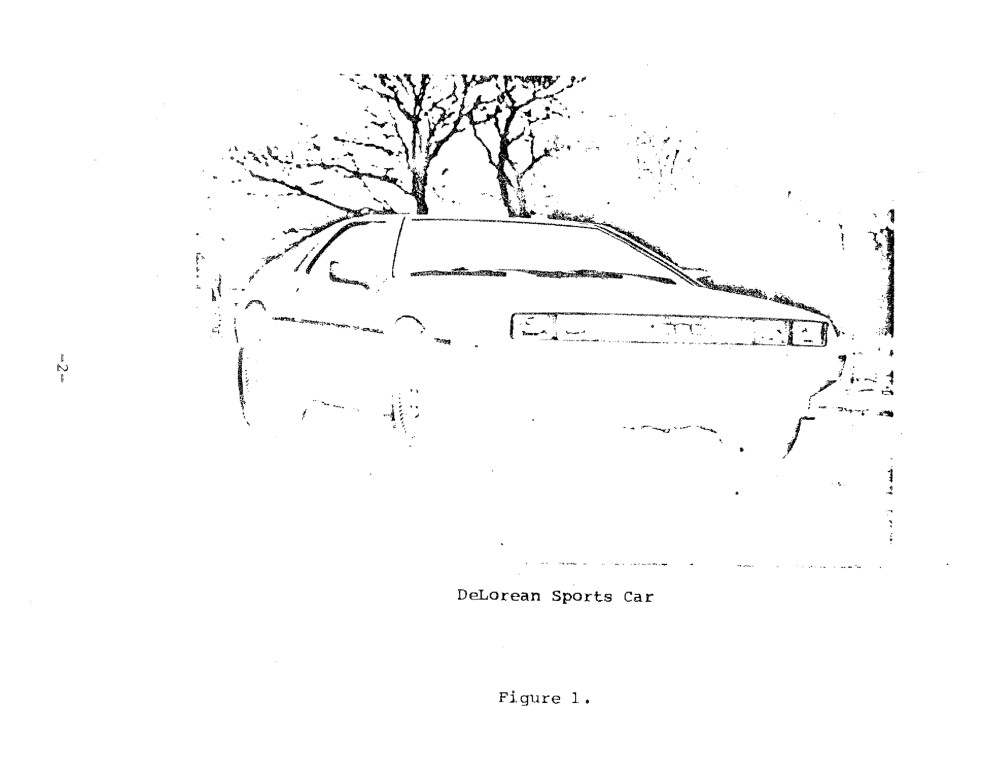
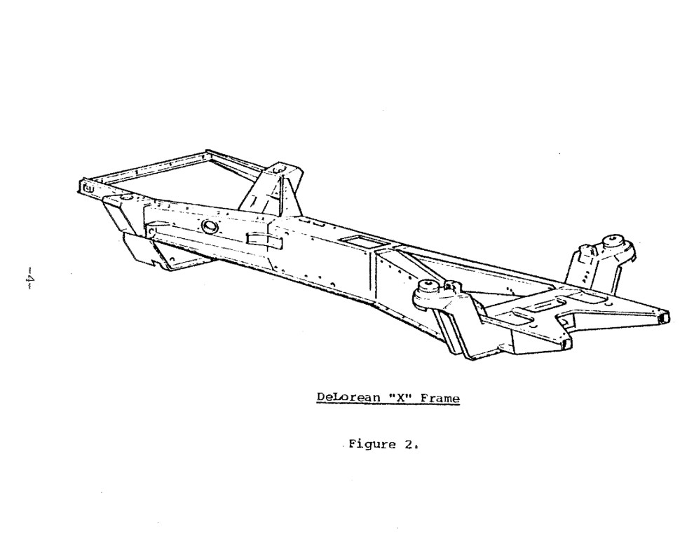
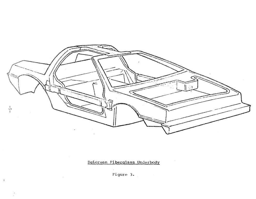
The vehicle chosen by NHTSA for this program was the DeLorean sports car. This vehicle is a two-passenger, rear engine car with gull wing doors and a stainless steel exterior skin as shown in Figure 1. The main structural frame is constructed of steel and roughly resembles an “X” with the middle of the X comprising the center spine that runs through the passenger compartment. Figure 2 shows this X-frame. Fastened to the main X-frame is a fiberglass body constructed glass reinforced panels and foam filled beams as shown in Figure 3. The vehicle curb weight is approximately 2700 lb.
Fitzpatrick Engineering’s main tasks in this contract were to:
a) Design a preliminary driver and passenger airbag restraint system using computer techniques,
b) Specify the restraint system components to be used in the two barrier crash tests and recommend test velocities.
c) Direct the test contractor, Dynamic Science, on the integration and installation of the restraint systems into the DeLorean.
d) Perform as Engineering Test Director for the two, frontal, barrier crash tests.
The purpose of these two crash tests were primarily to determine the structural response of the DeLorean at two different crash speeds and to provide an early indication of the performance potential of the computer derived restraint systems in this systems analysis approach to airbag integration.
2.0 Pre-Test Computer Simulations
Fitzpatrick Engineering studied existing crash data for the DeLorean at 30 mph as well as the passenger compartment interior design and volume and overall vehicle structural design. Based upon this study, we recommended that the test Speeds for the upcoming crash tests be 35 and 40 mph. This recommendation was made to representatives of NHTSA and DeLorean Motor Co, at a meeting held at DOT headquarters in Washington D.C.
In our judgement, the most information could be learned from these test speeds since the vehicle had already been crashed at 30 mph by DeLorean Motor Co. with very good structural performance and since the merits of the systems analysis approach Of restraint systems design would be tested more Severely at the higher impact speeds. However, since we didn’t know the Crash pulse at these higher speeds, the Preliminary computer simulations were of a qualitative nature. That is, we estimated the crash pulse at 35 and 40 mph based upon the 30 mph crash pulse and then conducted a series of computer runs in which we:
a) chose the airbag shapes and volumes,
b) evaluated eight different passenger inflators (including the possibility of using two “driver type” inflators instead of the one cylindrical type passenger inflator),
c) evaluated the restraint system performance at 10 and 15 msec sensing times to determine crash sensor specifications,
d) investigated the effect of staging the “driver type” inflators simulated for the passenger System to select the inflator configuration that would optimally satisfy the requirements of the forward positioned child as well as the normally seated adult.
In addition to the computer simulations, we made a subjective evaluation of the DeLorean interior to decide on the way the restraint system components would be installed in the vehicle. The result of the computer simulations using the DRAC and PAC computer models and this inspection of the vehicle led to conclusions that aided in selection of the preliminary airbag restraint system components as listed below.
Component – Type Selected – Basis for Selection
Steering Wheel – 1979 Volvo GT – Production DeLorean wheel does not have volume available for inflator and airbag installation. Volvo wheel does and also is designed to deform during crash. Stiffened spokes by addition of 0.067″ thick strap. Figure 4 shows Volvo wheel.
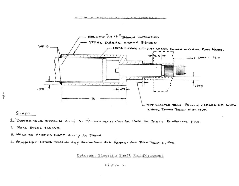
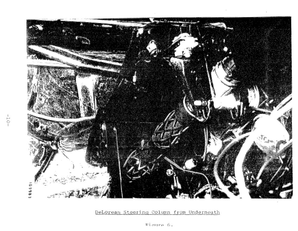
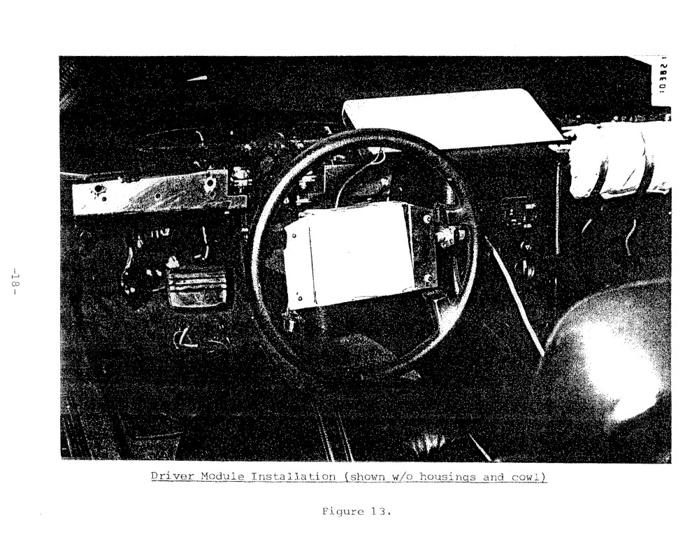
Steering Column – DeLorean with reinforced steering shaft (Figure 5) – Steering shaft reinforced to prevent bending as static tests indicated that shaft was “borderline.” Figure 6 shows underneath view after first crash test. Note tilt adjust mechanism.
Knee Restraint – Aluminum honeycomb – Dependable with known crush characteristics. Covered with aluminum skin with vinyl cover (Figure 7).
Inflator, Passenger – Thiokol / Mercedes – Selected two “driver type” inflators based upon computer predicted satisfactory performance for range of passenger sizes and positions. Also production line is set up.
Inflator, Driver – Thiokol / Mercedes – Used same inflator as on passenger side since predicted performance was satisfactory and a single part number could be used for all inflators in car. Figure 8 shows the inflators installed in driver and passenger modules.
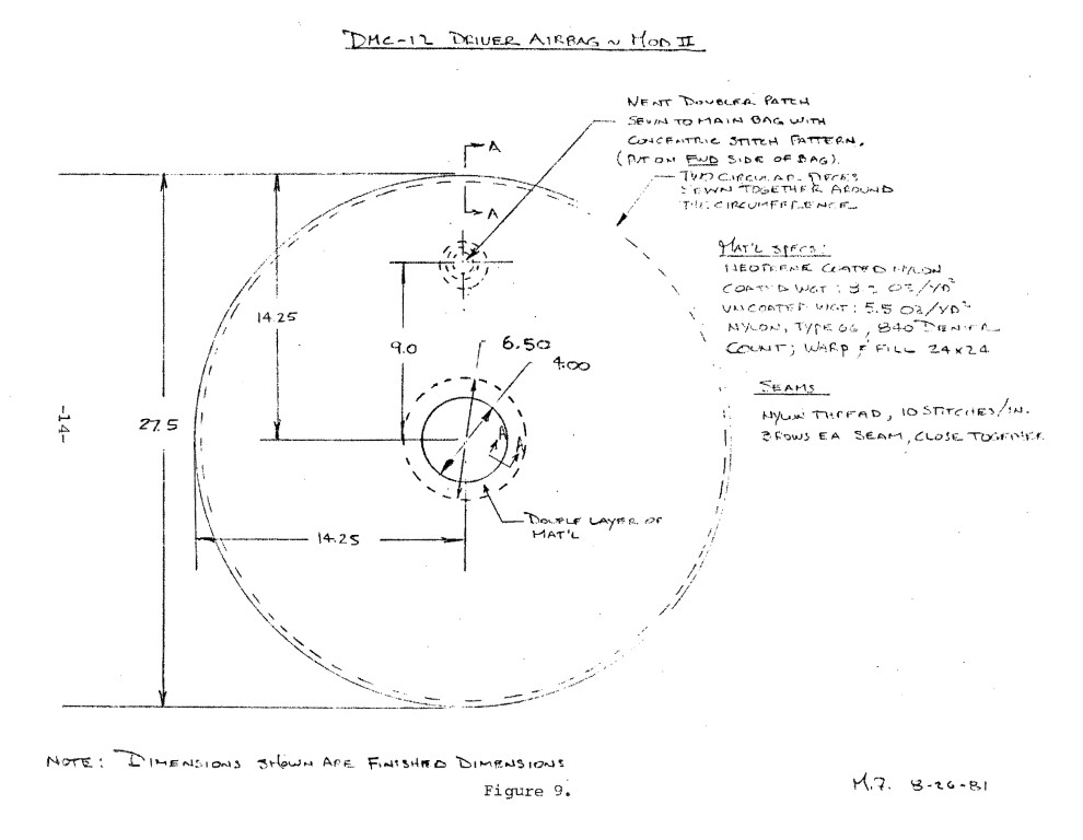
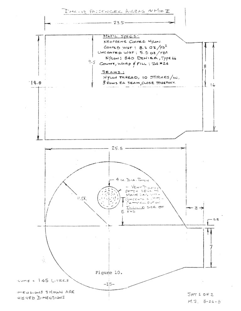
Airbags – Fitzpatrick Engineering design, Talley manufactured – Size, shape, volume and vent areas determined by computer simulation. Drawings furnished to Talley for manufacture (Figures 9 and 10).
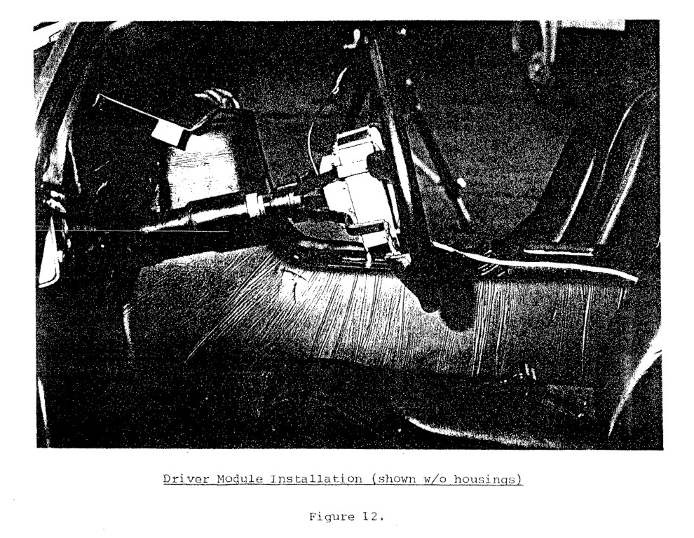
Packaging – Fitzpatrick Engineering design – Past experience used to design housings, adapters, modules and support structure to locate restraint systems in vehicle (Figs 11-16)


3.0 Integration of Restraint Systems into Vehicle
Once the computer derived restraint system components had been selected, ordered and finally obtained from the manufacturers, Fitzpatrick Engineering sent a representative to Dynamic Science, the NHTSA selected test contractor, to direct the integration of the restraint components into the first test vehicle. During this integration effort our Objective was to effect the integration in a cost effective manner that would be fairly typical of what, if not how, it Might be done introduction. That is, we attempted to use prototype shop techniques to fabricate structure that would approximate the method by which various restraint system components could be mounted. Very briefly, the method used was to bolt 12 gage sheet steel to the fiberglass A-Posts and tunnel to provide mounting surfaces for the knee restraints and the Passenger airbag module, By using this method of attachment and the relatively small module design shown in Figure 8, it was possible to effect this integration without infringing on the space occupied by the air conditioner or glove box.


4.0 Test Results
For these two preliminary crash tests it was mutually agreed
by the CTM and Fitzpatrick Engineering that the airbag inflation would be activated by a contact switch located on the bumper. In addition, this contact switch would operate in series with a built in electronic delay of ten milliseconds so that the computer selected delay of ten milliseconds from bumper contact until squib ignition would be realized. Again, based upon computer simulation, we decided to activate the driver airbag and the first level of the passenger airbag at the ten millisecond point but then wait another seven milliseconds to initiate the second Passenger inflator. In this way we could obtain a gas flow profile that was, theoretically at least, more satisfactory for both the normally seated adult and the forward positioned child.
The reason a contact switch was used rather than a crash sensor was due to the uncertainty as to the firing time we would obtain with commercially available sensors actuated by the, as yet unknown, DeLorean crash pulse. However, in order to learn as much as possible about what the sensing time of some commercially available sensors might be, three different types of sensors were *piggybacked” on the two tests.
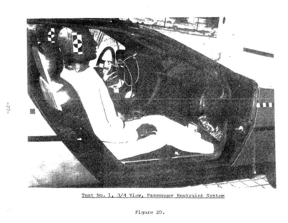
4.1 Crash Test No. 1
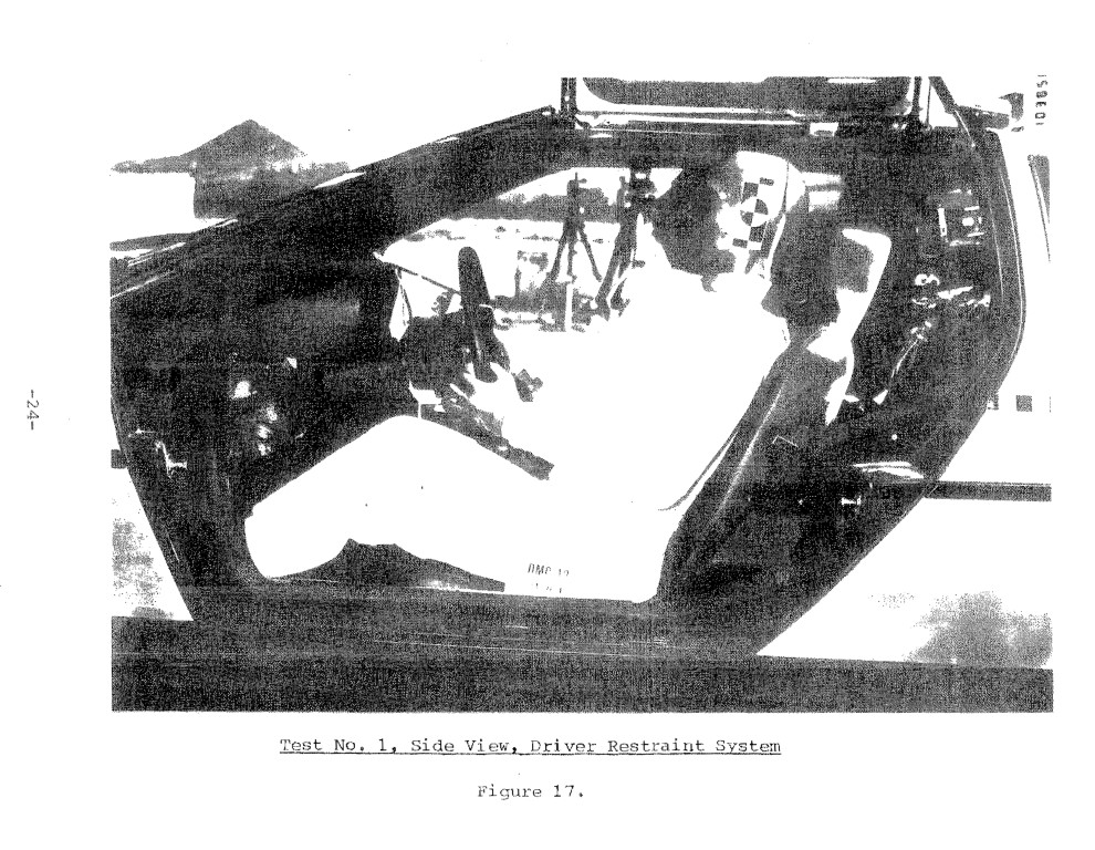
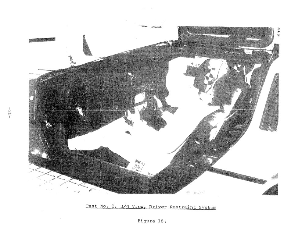
The first crash test was conducted on September 24, 1981 at a test speed of 36 mph and was a full frontal impact into a rigid barrier. In this first test the steering column was purposely prevented from stroking during dummy loading so that we could evaluate the performance of the other driver restraint system components – We especially wanted to determine whether the combination of the airbag and crushable steering wheel could absorb sufficient energy so that the stroking column would not be needed.
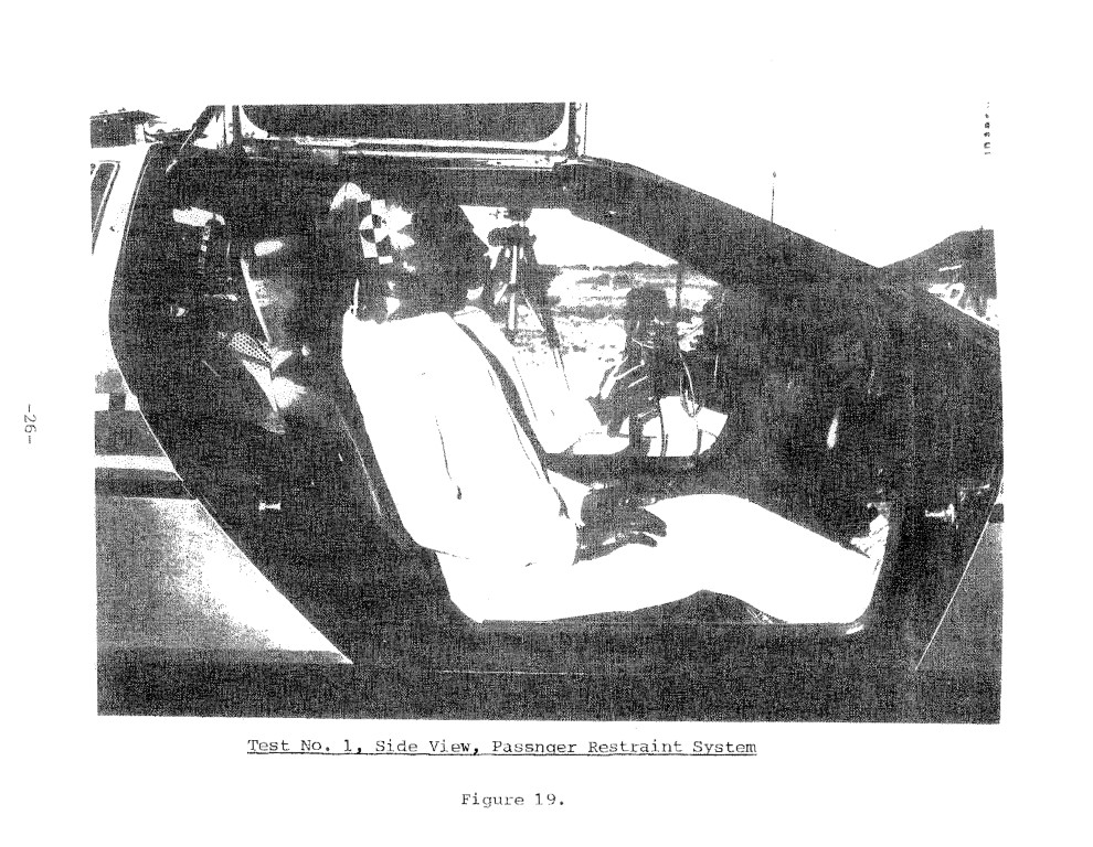
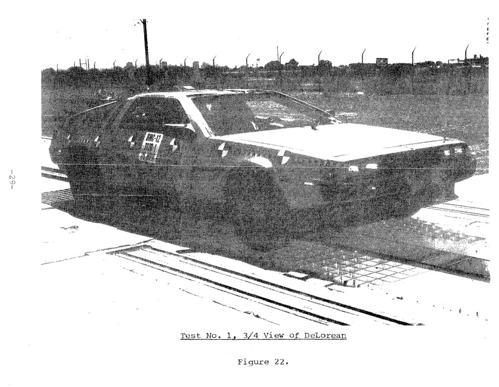
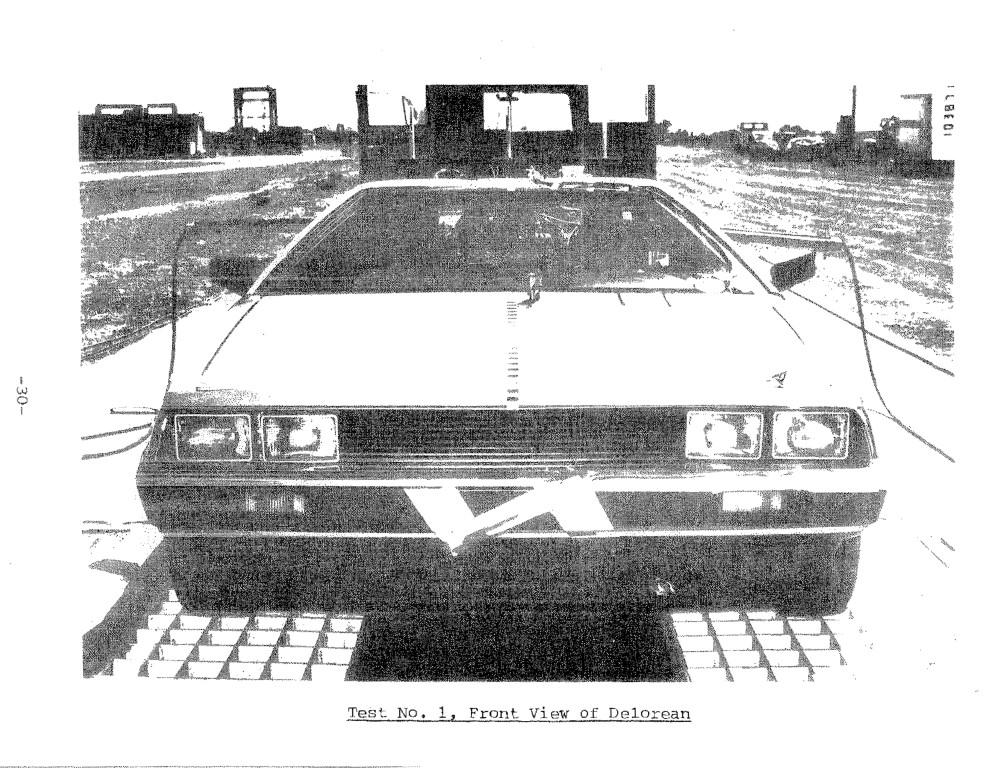
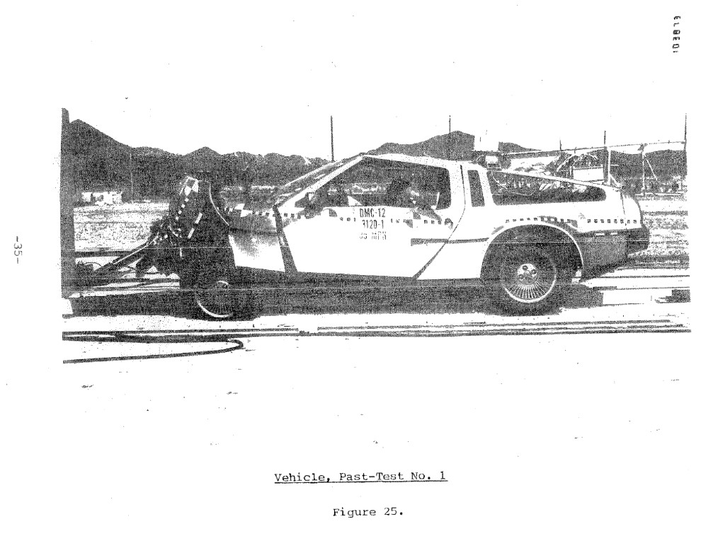
Figures 17 through 20 show the pre-test relationships between the 59th percentile dummies and their respective restraint systems. The seats were both placed in their mid-adjust, fore-aft positions. The test weight of the car with dummies, instrumentation and 5 gallons of Stoddard solvent in the fuel tank was 3351 lb. Figures 21 through 23 show the vehicle prior to test (although the doors were ajar when these photos were taken, they were securely latched before the test).
The dummy injury measures for this first test are shown in the table following the figures.

DeLorean Crash Test No. 1
36 MPH Frontal Barrier Test
Injury Measure – Driver – Passenger – “208” Limit
HIC – 404 – 371 – 1000
Peak Res. Chest G’s (-3 msec: ) – 44 – 42.5 – 60
Femur Loads ~Lbs
– Right – 1125 – 1050 – 2250
– Left – 840 – *1750(1220) – 2250
As may be seen in the table, the injury measures for this first test are quite low being well below the injury criteria limits.
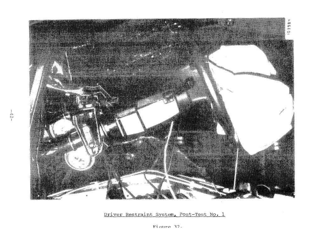
During this test the steering wheel crushed approximately two inches and the column rotated upward 104 degrees from its initial angle of 14 degrees from horizontal. In addition, the intruding firewall crushed approximately two inches of the expanded mesh E/A unit of the column (Figure 6).
The onboard “piggyback” sensors which were monitored to determine firing time performed as shown in the table on the next page.
*Believed to be noise spike in data since tension in femur is indicated only one msec after this spike. Number in parenthesis is maximum value if line is drawn through average values of noisy data.
Sensor Type – Location – Firing Time
GM BID – Underneath, aft of radiator, at the junction of the two front frame forks. – 47 msec
Bosch (3 ea. set for differ-firing times) – On tunnel between driver and passenger. – t1= 13 msec; t2 = 25.5 msec; t3= 29.5 msec
As may be seen, the sensors will need to be adjusted somewhat to obtain the 10 and 17 msec sensing times desired based upon computer simulation.
Although the test results were very encouraging, especially since there had been no preliminary sled testing in which preliminary restraint tuning had been done, we noticed two areas in which we believed improvement was possible.
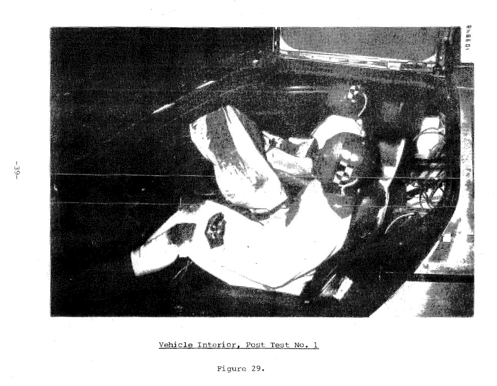
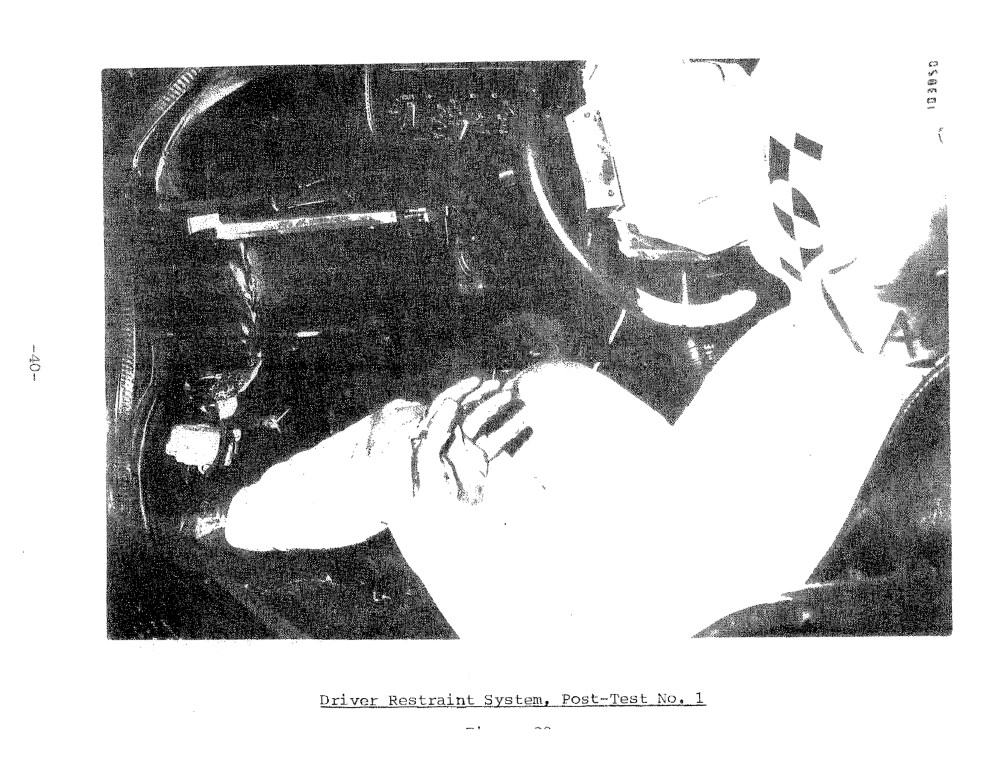
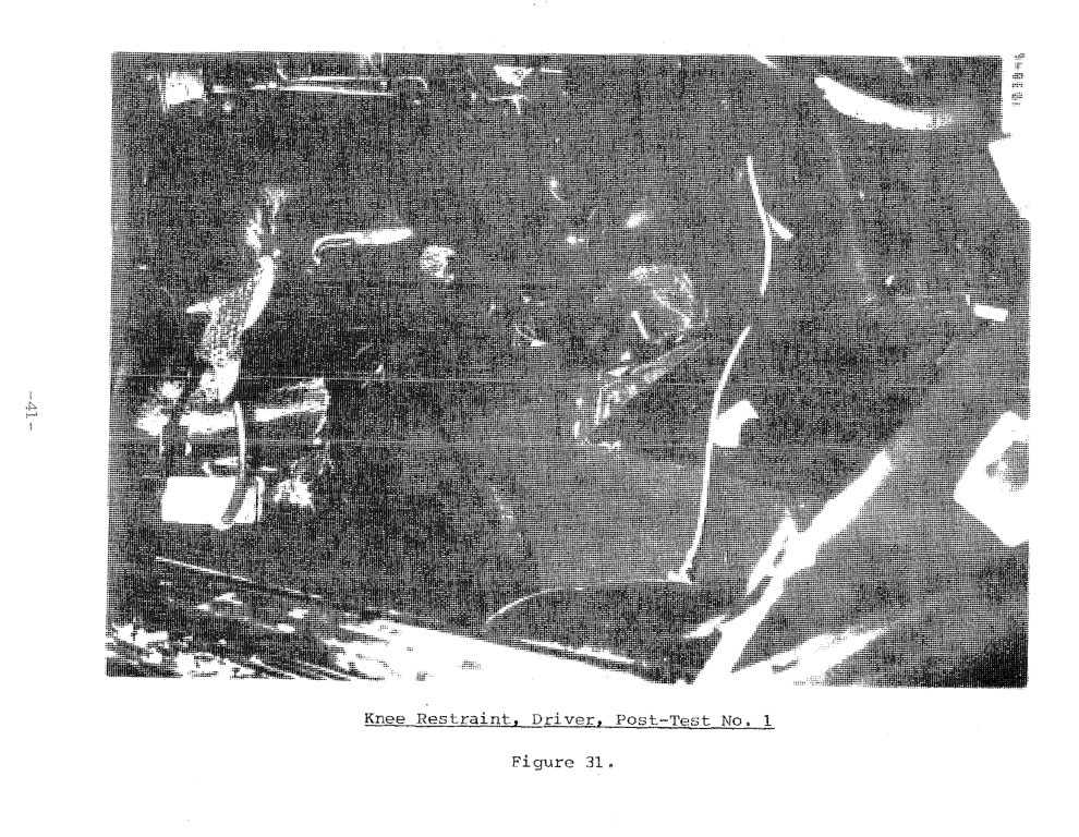
First, the driver “submarined” somewhat and, due to the non-stroking column used in this first test, his head was pushed rearward relative to the torso quite severely. Additionally, the driver H-point moved forward and then abruptly downward as the knees became imbedded in the knee restraint. This also contributed to the submarining tendency.
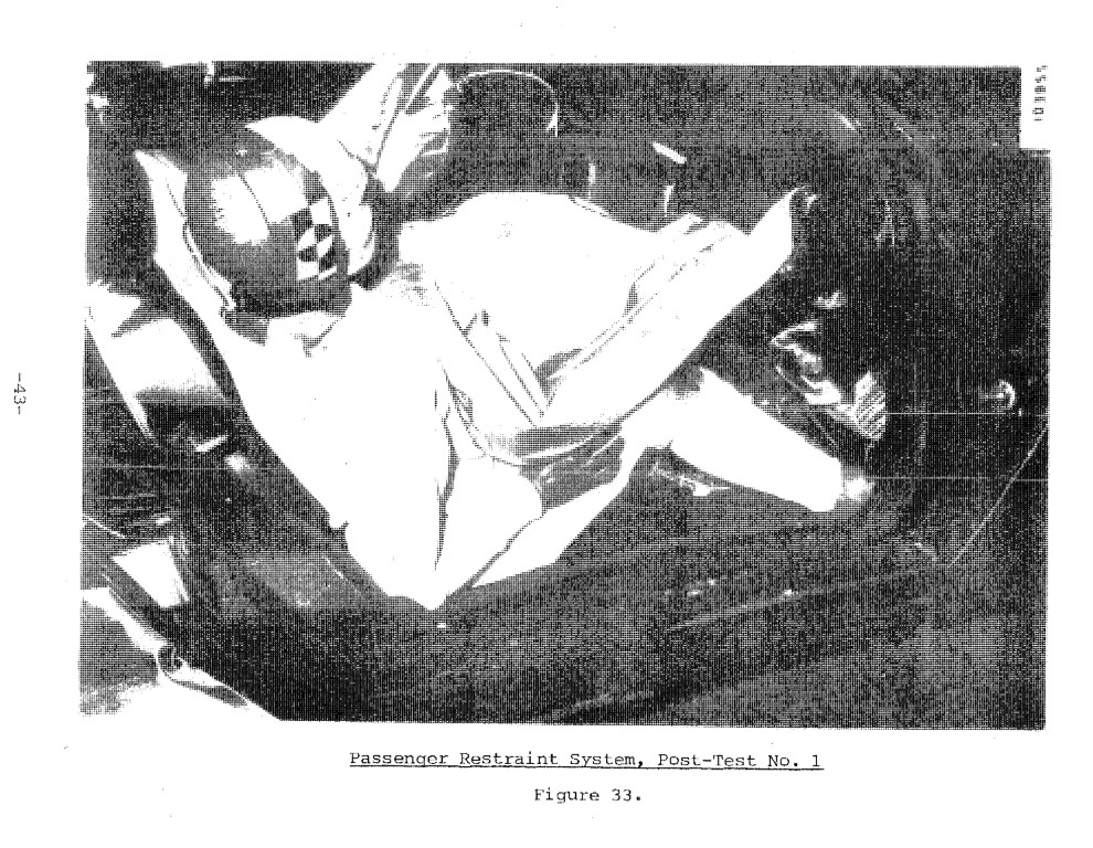
Seconds the passenger moved to the outboard side of his airbag, rotating in a counter-clockwise direction when viewed from above; i.e. so that he faced toward the driver somewhat.
Upon investigation we decided that this rotation was due to the fact that the passenger’s module pan containing the gas generators and the airbag were not pointing the airbag at the center of the passenger’s chest but was, rather, pointing toward the passenger’s left shoulder. The reason for this was that although the module pan was centered on the chest in the fore-aft direction, it was also canted to follow the dash contour thereby aiming the airbag toward the left shoulder.
To fix this prior to the next test, we merely rotated the module pan until its plane was perpendicular to the direction of vehicle travel. The effect of this rotation was that a line perpendicular to the center of the module pan now passed through the chest center.
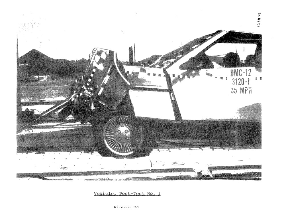
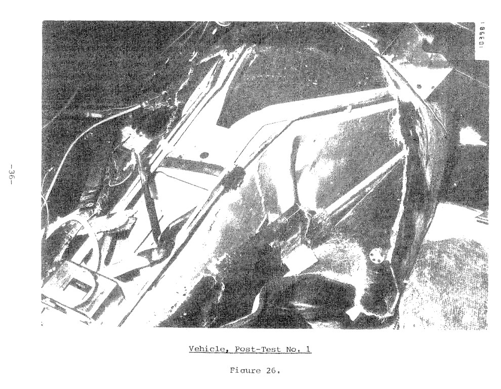
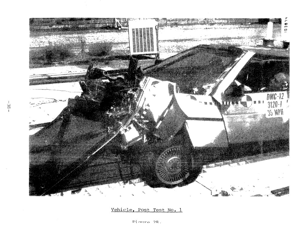
Figures 24 through 34 show the vehicle, dummies and restraint systems following the crash. There was only light-to-moderate structural intrusion into the passenger compartment and, what little there was, was confined to the lower firewall and toeboard areas.
All things considered, the test was very successful indicating that the systems analysis approach to restraint systems design and integration via computer simulation to have great potential in future design and integration efforts.
Appendix A contains the data traces from this first test.


-Page 45-
4.2 Crash Test No. 2
Based upon the promising results obtained in the first crash test, Fitzpatrick Engineering recommended to NHTSA and DeLorean Motor Co. that we increase the test speed to 40 mph for the next test. We made this recommendation to see if the satisfactory restraint systems performance predicted by the computer simulations for the assumed vehicle structural response would really hold up at this higher test speed. We also wanted to further verify the systems analysis approach to restraint systems design. Both parties agreed to the 40 mph test speed and plans went forward for the next test.
The test set-up in terms of restraint systems installation, dummy size and seat position were very similar to Test No. 1. The only areas where differences occurred were:
a) Passenger module pan was aligned to deploy airbag toward
chest centers
b) Steering column allowed to stroke and;
c) Vent area in driver airbag increased slightly from 1 1/4
inches to 1 5/8 inches diameter.
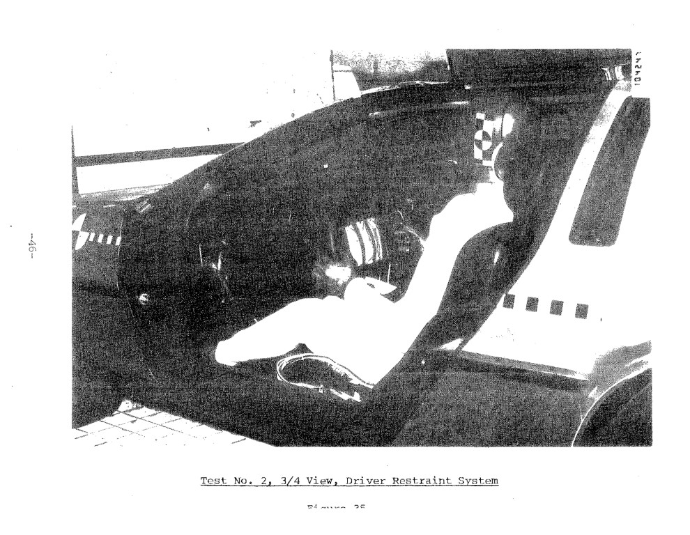
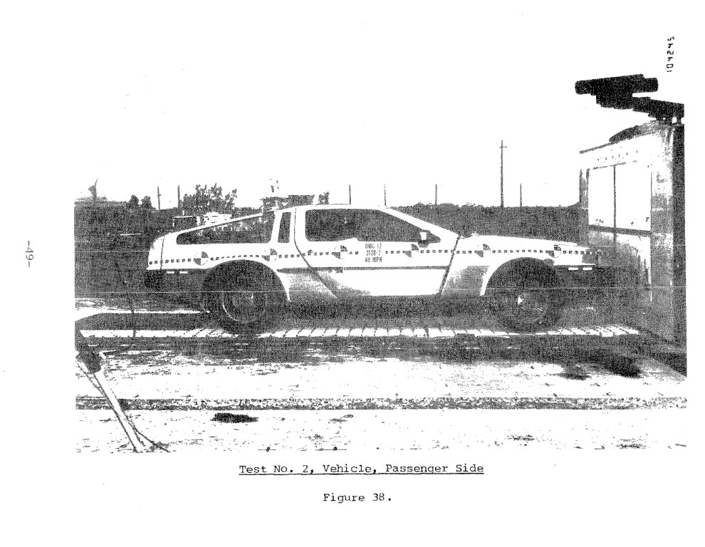
The second crash test was conducted on October 15, 1981 at a test speed of 40.6 mph. Again; the vehicle was impacted in a full frontal mode into a rigid barrier. Figures 35 and 36 show the pre-test restraint system/dummy configuration while Figures 37 and 38 show the vehicle. The test weight of the car with two dummies, instrumentation and 5 gallons of Stoddard solvent was 3347 lb.


-Page 50-
The injury measures for this second crash test are shown in the table below.
DeLorean Crash Test No. 2
41 MPH Frontal Barrier Test
Injury Measure – Driver – Passenger – “208” Limit
HIC – 366 – 684 – 1000
Peak Res. Chest G’s (-3 msec) – 46 – 52.5 – 60
Femur Loads – Lbs
– Right: – 1220 – 1160 – 2250
– Left: – 920 – *2110(1150) – 2250
As the table shows, the injury measures for this 40.6 mph barrier test are still well below the injury criteria limits shown in the right column.
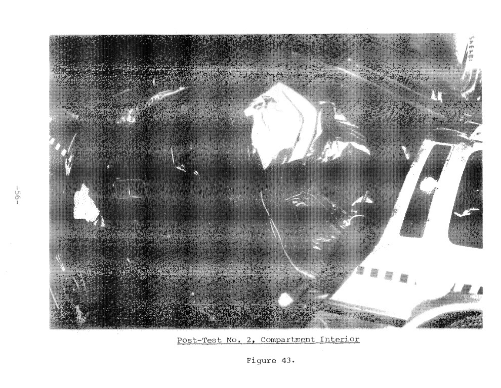
Although the outward appearance of the crashed vehicle looks as if the crash was quite severe (Figures 39 through 41), the opposite is true. The vehicle crushed approximately 44 inches but the intrusion into the passenger compartment was again confined to the lower firewall/toeboard area and some console axial collapse (Figure 42). In fact, the compartment interior dimensions following the crash were still quite generous so that most of the original compartment volume was maintained.
This may be seen by comparing Figures 35 and 43 on the driver side and Figures 36 and 42 on the passenger side which show pre and post test photos of the respective sides, It should be noted that the vehicles tested were pre-production prototypes with various cosmetic flaws. One problem we encountered was the driver door on the Test No. 2 vehicle. of the two door latches on the driver side ~ one forward and one rearward ~ we could at test time Only latch the forward latch, Because Of this, the aft side of the driver door came unlatched as it began to pick up load, thereby removing an important structural element from the driver Side. This was manifested by more crush on the driver Side and a net clock-wise rotation (when looking from above) of the entire vehicle during the test.
Another factor contributing to the degree of structural damage seen in the vehicle was the rather massive instrumentation: package located immediately behind the Seats. We therefore had a “worst case” situation for the vehicle structure. In spite of this worst case test condition however, the “survival Space” inside the compartment Was maintained so that the compartment interior dimensions were not greatly different than before the test.
As in Test No. 1, the steering column rotated upward another 10 to 11 degrees from horizontal for a final column angle of 25 degrees. Appendix B contains the data traces for Test No.2.
*The same note shown on page 31 applies here also. Since this is the same femur that was “noisy in Test No. 1, we suspect a faulty connector, wire or transducer in the right femur of passenger dummy.


-Page 57-
The steering column collapsed approximately six inches forward due to body applied forces. In addition, the intruding toeboard caused another two inches of crush for a total crush of 8 inches for the B/A unit. Figure 44 shows a post-crash, under-dash view of the crushed column. The pre-test length of the uncrushed, expanded metal mesh was 9% inches.
Again the on boards “piggyback” sensors were monitored to determine firing time.
Sensor Type – Location – Firing Time
GM BID – Underneath, aft of radiator at junction of two, front frame forks. – 43 msec
Bosch (3 level) – Tunnel, between driver and passenger. – t1 = 20 msec; t2=22 msec; t3=38 msec
CTAC (S/N 1206, 4 level) – Tunnel, between driver and pass. – t1 = 41 msec; t2 = 47 msec; t3 = 41 msec; t4 = 52 msec
Again, some lessening in sensing time will be required from these sensors prior to depending upon them to initiate airbag inflation.
Like Test No. 1, this test was also quite successful from several standpoints. First, and perhaps most importantly, we were able to show that the systems analysis approach to restraint systems design and integration via computer simulation can be a cost effective way of deriving restraint systems tailored to a specific vehicle’s crash environment.
Second, the Delorean proved to be a very well designed vehicle in terms of allowing a relatively great amount of front end crush without adversely compromising the “survival space” in the compartment.
And third, the low injury measures were obtained using “off-the-shelf” gas generators since the Thiokol/Mercedes units used were taken from the production line at the Thiokol facility. Further, all three of the driver type gas generators used were identical so as to obtain the cost advantages associated with larger production runs.
Obviously additional testing and system tuning is required for the restraint systems. Other crash modes should be investigated, out-of-position passengers tested, and other driver and passenger sizes analyzed. We believe, however, that these two preliminary crash tests show the restraint systems to have very good potential for eventual production installation in the DeLorean.
